Introduction
In any heat network, some transfer of heat between the pipes and their surroundings takes place. In district heat networks, heat losses from the pipes into the surrounding medium can be as significant as ~20% of the system’s total heat load. This can have a significant effect on both the efficiency and profitability of the heat network.
Accurate assessment of heat network heat losses requires data on pipework length, diameter, thickness and insulation for the specific network configuration. Since the purpose of the CHDU techno-economic model is to inform a nationwide search for sites where a heat network could be a viable option in decarbonising heating, rather than assess a specific site, a general rule of thumb for estimating heat loss is more useful.
This article describes the methodology that the CHDU techno-economic model uses to assess pipework heat losses within a network.
Key Factors Influencing Network Losses
Operating temperatures
Higher flow and return temperatures lead to higher heat losses across a network compared to lower temperatures. This is because heat loss is directly proportional to the temperature difference across a material, which in the case of a heat network is the temperature difference between the coolant in the network and the ambient ground temperature.
Network pipework length
The longer the length of the network, the greater the surface area of the network pipework, meaning there is a larger area across which heat can be lost.
Pipework size
In calculating heat losses, both the external and internal diameter of the pipe need to be considered, with thicker pipes tending to have lower heat loss.
Pipework insulation
The material from which the pipework insulation is made and its thickness is also a significant factor. Thicker insulation means less heat loss however it costs more and results in larger diameter pipes which cost more to install than smaller diameters. Larger diameter pipes may also be more difficult to install around existing utilities.
Pipework type
District heating pipework is available as single pipe or twin pipe. Twin pipe is constructed by containing separate flow and return pipework insulated within a single casing and has significantly less heat loss compared to single pipe.
Estimating Network Pipework Losses
Since the CHDU techno-economic model is intended to be used in a nationwide site search, without an understanding of the exact pipework layouts and connected buildings at different sites, it is not feasible to exactly assess network heat losses. Instead a regression analysis has been completed to estimate heat loss from network length and flow temperature, using outputs from 16 THERMOS simulations provided by Carbon Alternatives. Each simulation has modelled twin-pipes using the default THERMOS loss model with the networks predominantly serving domestic properties.
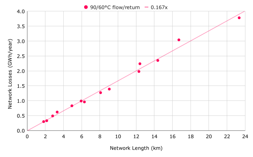
14 of the 16 THERMOS simulations were modelled with a flow/return temperature of 90/60oC. The two remaining simulations used a flow temperature of 70oC and have been discounted since there are not enough data points to derive a relationship. The absolute heat losses predicted by THERMOS for the 90/60oC simulations were plotted against the length of each network and a regression line was fitted. The relationship is very linear indicating that losses for domestic networks are directly proportional to network length for a given flow/return temperature.
This relationship is built into the CHDU techno-economic model enabling pipework heat losses to be estimated from flow temperature and network length. Flow temperature is a variable that is specified by the user of the model, and network length is a spatially derived value specific to individual heat network sites.

How Network Losses are Modelled
The relationship between network pipework losses and network length presented in Figure 1 is built into the model after being linearly reduced to represent losses for a network operating at 65/45 flow/return temperature (the initial target operating temperatures assumed in the CHDU techno-economic model). Network length is derived based on the building density and network area, as described in the Network Length article on this site, and applied to the heat losses relationship to calculate a heat loss value for the network.
In addition to pipework losses, a value for losses at the heat interface units in each property within the network are included at 0.7kWh/day per connection. This is as recommended by the CIBSE CP1 code of practice.
This total annual heat loss value is spread evenly across the hourly heat demand profile of the network. The electrical demand of the heat pumps and fuel demand of the back-up boilers is then calculated based on this hourly profile.
References
THERMOS, https://tool.thermos-project.eu/help/network/technical-description.html#pipe-heat-losses
CIBSE, CP1 Heat networks: Code of Practice for the UK, https://www.cibse.org/knowledge-research/knowledge-portal/cp1-heat-networks-code-of-practice-for-the-uk-2020-pdf
Banner Image Attribution:
Image sourced from commons.wikimedia.org available in the public domain.